In the next few lines we will present you a welding joint, in two constructive solutions. It remains at your choice which one you will decide to use, when and how.
So, this have been told, let’s start. First of all what is a welding joint? A short description may be : a technological process of permanent joining of metals and alloys, by local melting, with or without additional material.
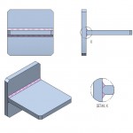
In order to have a subject of discussion, we choose a “T” joint – which is often seen in industry.
In order to do that we have made 3 plates, with equal dimensions, but have some different details. The first plate is a square plate, having the dimensions of 100 x 100 x 10 [mm], which has the corners chamfered at 5 x 45° – more for an aesthetic rison instead of a functional one.

Plate 100 x 100 x 10 [mm] – with chamfers of 5×45°
The second plate that we will use has the dimensions of 100 x 100 x 10 [mm]. At this one we will chamfer only two corners at 5 x 45°.
 Plate 100 x 100 x 10 [mm] – with chamfers of 5 x 45° only at two corners
Tha third one (and the last one) has the dimensions of 100 x 100 x 10 [mm]. Also at this plate we will chamfer only 2 edges at 5×45°. This one instead has two more chamfers at 5×45° as you can see in the “X” Detail in the bellow picture. Why did we do that? You will see in the next lines.

Plate 100 x 100 x 10 [mm] – with chamfers of 5 x 45° in two planes
Until here, nothing new! Just presenting two types of welding. Now instead is the time put ourselves some questions like: which one holds better, which are the advantages / disadvantages when using one of them. In order to be able to answer to this questions we use a FEM analysis. First of all we set the material. We will use a common steel : S235 JR. Applied force : 2000 [N].
Further, in order to make a better evaluation, we decided to study the parts presented above, by the loads applied, so we have:
- bending load;
- axial load;
- combind load – bedning + axial;
That said, we have the next situations, presented bellow :

Bending load

Axial load

Combined load
After running the analysis, for the first case, we have the next results:
 Deformations and maximum stress when bending load

Deformations and maximum stress when axial load

Deformations and maximum stress when combined load ( axial + bending )
After running the analysis, for the second case, we have the next results:

Deformations and maximum stress when bending load
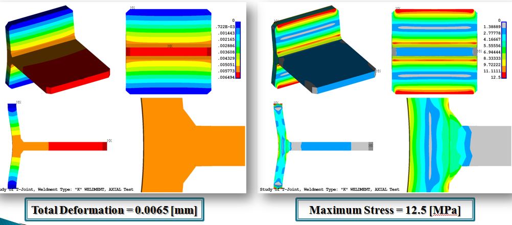
Deformations and maximum stress when axial load

Deformations and maximum stress when combined load ( axial + bending )
Everything is ok. To be completely synthesized, below we present a table with all the data we are interested.
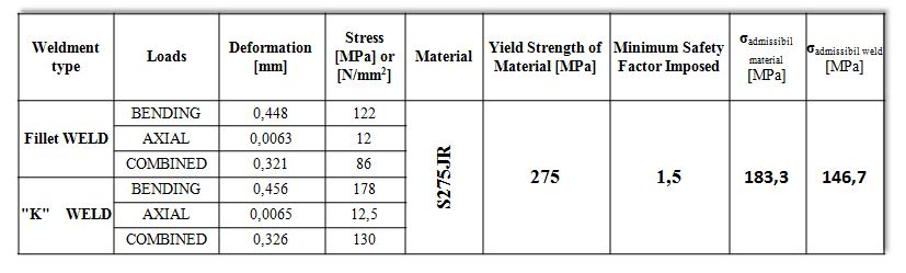
Table with the results
To have a much clear image of the results, we offer you the next two graphs:
 Deformations
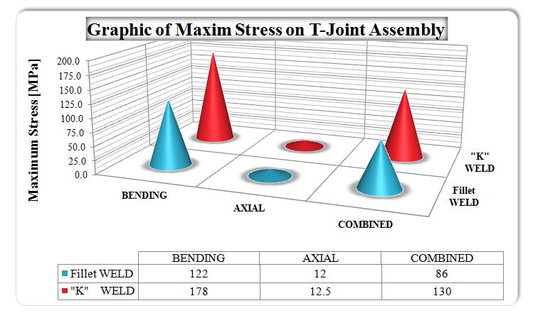
Stress
We arrived now at the moment where we present our conlcusions :
- From the graphical results presented in above, can be observe that the most unsafe assembly is where “K” weld type is use (from the point of view of maximum stress);
- From the point of displacement, can be observed that the higher displacements are present as well where the “K” weld type is use;
- In the cases studied and presented, can be observe the maximum stress is present always in vicinity of weld. The principal reason is because the maximum stress occurs only in “K” weld type is the higher stiffness increased local by the type of weld.
- Correct correlation of wall thickness for those parts which are machined with type of applied loads and locations where are applied loads. From study result that the thickness of horizontal plate must be increase due to their admissible stress on limit of material.
- As general conclusion, the most stiffness assembly is where “K” weld is use, and on the other side the most elastic assembly is where fillet weld is use.
It is up to each of you to choose one of the options above. This article was made strictly for educational purposes, to present to the concerned persons and not having access to certain information the two cases – quite common in the work of a mechanical engineer. We also accept that we can discuss a lot on these cases presented. Size, material, loads were chosen only to highlight deformations and stresses – under no circumstances is any practical case.
Thank you!
Mech-Design TEAM